

|
|
|
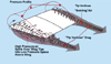
Wing-tip vortices are formed when high-pressure air spills up over the wing tips into the low-pressure space above the wing.
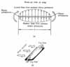
Pressures must become equal at the wing tips since pressure is a continuous function (figure a). The free stream flow combines with tip flow, resulting in an inward flow of air on the upper wing surface and an outward flow of air on the lower wing surface (figure b).
Formation of wing-tip vortices.
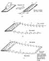
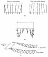
Complete-wing vortex system.
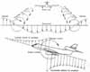
Vortex flow effects produced by a jet plane. The upwash and the downwash are due to both the bound vortex and the tip vortices.

Upwash and downwash fields around an airplane create turbulence in flight.

Effect of aspect ratio on coefficient of lift.
|
Wing VorticesVortices form because of the difference in pressure between the upper and lower surfaces of a wing that is operating at a positive lift. Since pressure is a continuous function, the pressures must become equal at the wing tips. The tendency is for particles of air to move from the lower wing surface around the wing tip to the upper surface (from the region of high pressure to the region of low pressure) so that the pressure becomes equal above and below the wing. In addition, there exists the oncoming free-stream flow of air approaching the wing. If these two movements of air are combined, there is an inclined inward flow of air on the upper wing surface and an inclined outward flow of air on the lower wing surface. The flow is strongest at the wing tips and decreases to zero at the midspan point as evidenced by the flow direction there being parallel to the free-stream direction. When the air leaves the trailing edge of the wing, the air from the upper surface is inclined to that from the lower surface, and helical paths, or vortices, result. A whole line of vortices trails back from the wing, the vortex being strongest at the tips and decreasing rapidly to zero at midspan. A short distance downstream, the vortices roll up and combine into two distinct cylindrical vortices that constitute the "tip vortices." The tip vortices trail back from the wing tips and they have a tendency to sink and roll toward each other downstream of the wing. Again, eventually the tip vortices dissipate, their energy being transformed by viscosity. The tip vortices cause additional downflow (or downwash) behind the wing within the wingspan. For an observer fixed in the air, all the air within the vortex system is moving downward (called downwash) whereas all the air outside the vortex system is moving upward (called upwash). An aircraft flying perpendicular to the flight path of the airplane creating the vortex pattern will encounter upwash, downwash, and upwash in that order. The gradient, or change of downwash to upwash, can become very large at the tip vortices and cause extreme motions in the airplane flying through it. An airplane flying into a tip vortex also has a large tendency to roll over. If the control surfaces of the airplane are not effective enough to counteract the airplane roll tendency, the pilot may lose control or, in a violent case, experience structural failure. The takeoff and landings of the new generation of jumbo jets compound the problems of severe tip vortices. During takeoff and landing, the speed of the airplane is low and the airplane is operating at high lift coefficients to maintain flight. The Federal Aviation Agency (FAA) has shown that for a 600 000-pound (2.7 million-kilogram) plane, the tip vortices may extend back strongly for five miles (eight kilometers) from the airplane and the downwash may approach 160 meters per minute (500 ft/min). Tests also show that a small light aircraft flying into a vortex could be rolled over at rates exceeding 90 degrees per second. —Adapted from Talay, Theodore A. Introduction to the Aerodynamics of Flight. SP-367, Scientific and Technical Information Office, National Aeronautics and Space Administration, Washington, D.C. 1975. Available at http://history.nasa.gov/SP-367/cover367.htm For Further Reading: Anderson, Jr., John D. A History of Aerodynamics. Cambridge, England: Cambridge University Press, 1997. Smith, H.C. “Skip.” The Illustrated Guide to Aerodynamics, 2nd edition. Blue Ridge Summit, Pa.: TAB Books, 1992. Wegener, Peter P. What Makes Airplanes Fly? New York: Springer-Verlag, 1991. “Boundary Layer Separation and Pressure Drag.” University of Virginia Department of Physics. http://www.phys.virginia.edu/classes/311/notes/fluids2/node11.html “Drag.” Lego Design and Programming System. http://ldaps.ivv.nasa.gov/Physics/drag.html
|